 National Radio
Astronomy Observatory
|
|
|||
| NRAO Home > CASA > CASA Cookbook and User Reference Manual |
|
||
2.1.1 Under the Hood: Structure of the Measurement Set
It is not necessary that a casual CASA user know the specific details on how the data in the MS is stored and the contents of all the sub-tables. However, we will occasionally refer to specific “columns” of the MS when describing the actions of various tasks, and thus we provide the following synopsis to familiarize the user with the necessary nomenclature. You may skip ahead to subsequent sections if you like!
All CASA data files, including Measurement Sets, are written into the current working directory by default, with each CASA table represented as a separate sub-directory. MS names therefore need only comply with UNIX file or directory naming conventions, and can be referred to from within CASA directly, or via full path names.
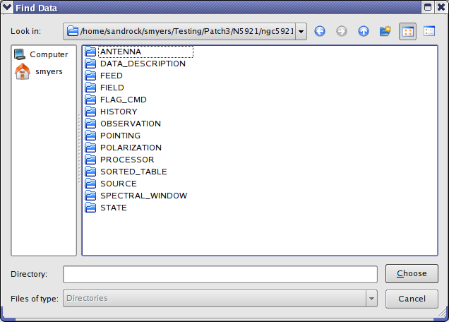
An MS consists of a MAIN table containing the visibility data. and associated sub-tables containing auxiliary or secondary information. The tables are logical constructs, with contents located in the physical table.* files on disk. The MAIN table consists of the table.* files in the main directory of the ms-file itself, and the other tables are in the respective subdirectories. The various MS tables and sub-tables can be seen by listing the contents of the MS directory itself (e.g. using Unix ls), or via the browsetable task (§ 3.8).
See Fig 2.1 for an example of the contents of a MS directory. Or, from the casapy prompt,
IPython system call: ls -F ngc5921.ms
ANTENNA POLARIZATION table.f1 table.f3_TSM1 table.f8
DATA_DESCRIPTION PROCESSOR table.f10 table.f4 table.f8_TSM1
FEED SORTED_TABLE table.f10_TSM1 table.f5 table.f9
FIELD SOURCE table.f11 table.f5_TSM1 table.f9_TSM1
FLAG_CMD SPECTRAL_WINDOW table.f11_TSM1 table.f6 table.info
HISTORY STATE table.f2 table.f6_TSM0 table.lock
OBSERVATION table.dat table.f2_TSM1 table.f7
POINTING table.f0 table.f3 table.f7_TSM1
Note that the MAIN table information is contained in the table.* files in this directory. Each of the sub-table sub-directories contain their own table.dat and other files, e.g.
IPython system call: ls -F ngc5921.ms/SOURCE
table.dat table.f0 table.f0i table.info table.lock
_________________________________________________________________________________________
Each “row” in a table contains entries for a number of specified “columns”. For example, in the MAIN table of the MS, the original visibility data is contained in the DATA column — each “cell” contains a matrix of observed complex visibilities for that row at a single time stamp, for a single baseline in a single spectral window. The shape of the data matrix is given by the number of channels and the number of correlations (voltage-products) formed by the correlator for an array.
Table 2.1 lists the non-data columns of the MAIN table that are most important during a typical data reduction session. Table 2.2 lists the key data columns of the MAIN table of an interferometer MS. The MS produced by fillers for specific instruments may insert special columns, such as ALMA_PHASE_CORR, ALMA_NO_PHAS_CORR and ALMA_PHAS_CORR_FLAG_ROW for ALMA data filled using the importasdm filler (§ 2.2.1). These columns are visible in browsetable and are accessible from the toolkit in the ms tool (e.g. the ms.getdata method) and from the tb “table” tool (e.g. using tb.getcol).
Note that when you examine table entries for IDs such as FIELD_ID or DATA_DESC_ID, you will see 0-based numbers.
| Parameter | Contents |
| ANTENNA1 | First antenna in baseline |
| ANTENNA2 | Second antenna in baseline |
| FIELD_ID | Field (source no.) identification |
| DATA_DESC_ID | Spectral window number, polarization identifier pair (IF no.) |
| ARRAY_ID | Subarray number |
| OBSERVATION_ID | Observation identification |
| POLARIZATION_ID | Polarization identification |
| SCAN_NUMBER | Scan number |
| TIME | Integration midpoint time |
| UVW | UVW coordinates |
The MS can contain a number of “scratch” columns, which are used to hold useful versions of other columns such as the data or weights for further processing. The most common scratch columns are:
- CORRECTED_DATA — used to hold calibrated data for imaging or display;
- MODEL_DATA — holds the Fourier inversion of a particular model image for calibration or imaging. this column is optional from CASA 3.4 and higher and typically not required anymore
The creation and use of the scratch columns is generally done behind the scenes, but you should be aware that they are there (and when they are used).
| Column | Format | Contents |
| DATA | Complex(Nc, Nf) | complex visibility data matrix (= ALMA_PHASE_CORR by default) |
| FLAG | Bool(Nc, Nf) | cumulative data flags |
| WEIGHT | Float(Nc) | weight for a row |
| WEIGHT_SPECTRUM | Float(Nc, Nf) | individual weights for a data matrix |
| ALMA_PHASE_CORR | Complex(Nc, Nf) | on-line phase corrected data (Not in VLA data) |
| ALMA_NO_PHAS_CORR | Bool(Nc, Nf) | data that has not been phase corrected (Not in VLA data) |
| ALMA_PHAS_CORR_FLAG_ROW | Bool(Nc, Nf) | flag to use phase-corrected data or not (not in VLA data) |
| MODEL_DATA | Complex(Nc, Nf) | Scratch: created by calibrater or imager tools |
| CORRECTED_DATA | Complex(Nc, Nf) | Scratch: created by calibrater or imager tools |
The most recent specification for the MS is Aips++ MeasurementSet definition version 2.0 (http://casa.nrao.edu/Memos/229.html).
More information about CASA may be found at the
CASA web page
Copyright © 2010 Associated Universities Inc., Washington, D.C.
This code is available under the terms of the GNU General Public Lincense
Home |
Contact Us |
Directories |
Site Map |
Help |
Privacy Policy |
Search