News News |
FAQ
|
| Search
|
Home
|
| Getting Started | Documentation | Glish | Learn More | Programming | Contact Us |
|
| Version 1.9 Build 1556 |
|


For a given interferometer, the measured visibilities for a point
source in the centre of the field! can be described by a 4-element
`coherency vector' ![]() , which is related to the so-called
`Stokes visibility vector'
, which is related to the so-called
`Stokes visibility vector'
![]() = (I, Q, U, V)ijT of
the observed source by a matrix operation,
= (I, Q, U, V)ijT of
the observed source by a matrix operation,
Here subscripts p and q represent the two polarisation
channels measured by each antenna. (NB: They are named X and
Y for WSRT and ATCA, and R and L for the VLA).
The subscripts i and j represent the antenna numbers, and
![]() represents the matrix direct product (also called the
tensor product, or Kronecker product).
represents the matrix direct product (also called the
tensor product, or Kronecker product).
The Stokes visibility vector depends on the brightness distribution
and on the length and orientation of baseline ij. The 4 x 4
matrix ![]() converts it into a coherency vector (ignoring
instrumental effects).
converts it into a coherency vector (ignoring
instrumental effects). ![]() is unitary, except for a normalising
constant:
is unitary, except for a normalising
constant:
![]() = 2
= 2![]() . It cannot be decomposed into
antenna-based parts.
. It cannot be decomposed into
antenna-based parts.
The 4-element vector
![]() represents additive
interferometer-based effects. Examples are receiver noise, and
correlator offsets. The 4 x 4 diagonal matrix
represents additive
interferometer-based effects. Examples are receiver noise, and
correlator offsets. The 4 x 4 diagonal matrix
![]() represents multiplicative interferometer-based effects, which
cannot be factored into antenna-based contributions. Examples are
decorrelations, which usually give diagonal matrices with identical
elements. Fortunately, the elements of
represents multiplicative interferometer-based effects, which
cannot be factored into antenna-based contributions. Examples are
decorrelations, which usually give diagonal matrices with identical
elements. Fortunately, the elements of
![]() and
and
![]() tend to be small or close to unity in practice, and
will be ignored here.
tend to be small or close to unity in practice, and
will be ignored here.
Thus it is assumed that, in the case of a central point source, all
instrumental effects can be factorised into antenna-based
contributions. The 4 x 4 interferometer response matrix
![]()
![]()
![]() then consists of a direct
matrix product of two 2 x 2 antenna-based response
matrices.1
The reader will note that this is the
polarimetric generalisation of the familiar `Selfcal assumption'.
then consists of a direct
matrix product of two 2 x 2 antenna-based response
matrices.1
The reader will note that this is the
polarimetric generalisation of the familiar `Selfcal assumption'.
This antenna response matrix ![]() can be decomposed into a
product of matrices, each of which models a specific instrumental
effect in the signal path.2
can be decomposed into a
product of matrices, each of which models a specific instrumental
effect in the signal path.2
in which,
NB: It is wrong to identify IF-channels with receptors, like the X and Y dipoles at WSRT or ATCA. In a VLA antenna, the circularly polarised IF-signals are a combination of the signals of the two linear dipoles. Another example: in the ATCA and the new WSRT frontends, the signals from the dipoles may be rapidly switched between IF-channels, for calibration purposes.
NB: Other processes may also contribute to leakage. For example, cross-talk between the two IF-channels can be described by adding a non-zero mutual coupling factor ci to the off-diagonal terms.
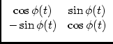
It should be noted that these matrices generally do not commute, so
that their order is important! For instance, a diagonal matrix like
![]() does not commute with a matrix with non-zero
elements off the diagonal, like
does not commute with a matrix with non-zero
elements off the diagonal, like
![]() . Thus, one should be a
little careful in sweeping all complex gain effects into a
single matrix
. Thus, one should be a
little careful in sweeping all complex gain effects into a
single matrix
![]() , irrespective of where they occur in the
signal path.
, irrespective of where they occur in the
signal path.
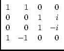
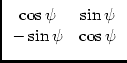
Matrices
![]() ,
,
![]() and
and
![]() are Cartesian
coordinate transforms, and thus unitary:
are Cartesian
coordinate transforms, and thus unitary:
![]() =
= ![]() .
Matrix
.
Matrix
![]() is not unitary if it represents a conversion from
linear to circular polarisation (..?). Do they commute??
is not unitary if it represents a conversion from
linear to circular polarisation (..?). Do they commute??