News News |
FAQ
|
| Search
|
Home
|
| Getting Started | Documentation | Glish | Learn More | Programming | Contact Us |
|
| Version 1.9 Build 1488 |
|


| Package | general | |
| Module | images |
include "imagefitter.g"
| imagefitter | Construct an Imagefitter |
| componentlist | Recover the fitted components |
| done | Destroy this Imagefitter tool |
| gui | Start the GUI interface |
| nfits | Return number of accepted fits |
| regions | Recover fitted regions |
| setmaxpixels | Set maximum number of pixels to fit without query |
| summary | Summarize the image being fitted |
| type | What type is this tool ? |
![[*]](../../gif/latex2html/cross_ref_motif.gif) |
Synopsis
The Imagefitter tool offers interactive fitting of 2D models (or components) to an image of the sky. You control the process from a GUI interface. The tool is self contained. Thus, the display is built into the interface.
Current functionality includes
Restrictions which will be removed with time are currently
There will be some interface changes as these things are accomodated.
More Details
It is useful for you to know a little about how the Imagefitter manages the resultant fitted parameters. Each 'fit' that you make may contain multiple components. For example, you might fit three gaussians simultaneously. The Imagefitter stores the result of each accepted fit in its own Componentlist tool. In reality it maintains a list of Componentlist tools and you can manipulate this list in a few ways. You can display (make graphical overlay on display) any or all of the Componentlist tools in the list (via the Show/Hide buttons on the main GUI). You may delete any or all of the Componentlist tools in the list (via the Delete button on the main GUI). You can recover all or any of the Componentlist tools in the list (via function componentlist).
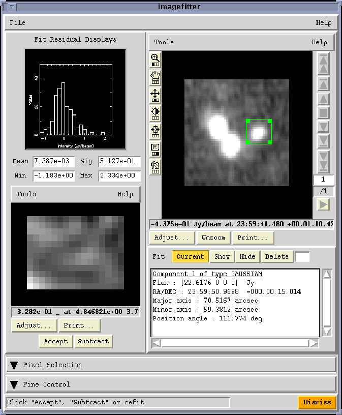
Here is an example of the basic Imagefitter GUI.
Under the ``File'' menu at the top you find the following items.
The GUI shows a display of the image to the right. Beneath the image is a listbox showing the parameters of the model fits. To the left are a range of displays for the residuals of the fits. At the top is a histogram and some statistics. Below that is an image of the residuals in the fitted region.
There are two rollups beneath the data displays.
The first is labelled ``Pixel Selection''. With this widget, you can select which pixels, by intensity range, will be fit - it is generally good to exclude noise pixels. You can set an inclusion range, an exclusion range, or use an auto pixel selection. This last mode selects pixels depending on the context. For Stokes I, positive pixels are selected if the absolute peak in the fitting region is positive. It selects negative pixels if the peak is negative. For other Stokes parameters, all pixels are selected. You may wish to fine tune the pixel selection range so that only pixels above the noise level are selected.
Also in this rollup is an entry box labelled 'Maximum pixels'. If you ask to fit a large number of pixels (perhaps you forgot to set a region), the fit may go for a semi-infinite time. To protect against this, there is a built in maximum number of pixels allowed. If you ask to fit more pixels than this, you are queried whether you wish to proceed through a choice GUI. You can set this maximum pixels query limit to something different here (perhaps make it larger).
The second rollup is labelled ``Fine Control''. This is where you can activate the advanced interface. You select the number of simultaneous components you wish to fit (either type it in or move the slider) and then press the ``Go'' button.
Finally, a message line below the rollups provides you with information on what to do next. The Imagefitter constrains you as much as it can so that the only things you can do are valid.
The Basic Interface
If you don't activate the advanced interface, you get the basic interface. This means that
The fitting process is triggered by you generating a region (rectangle or polygon) and double clicking within it to signify it is ready. After the fit is done, the parameters are displayed in the list box, and the residual image, histogram and statistics are displayed. At this point, you can press the ``Accept'' button to accept and store the fit internally. Otherwise you can just do another fit.
At any point you can press the ``Subtract'' button. This subtracts the last fitted model from the data and the main image display is updated to reflect this. Once the ``Subtract'' button is pressed, it becomes an ``Add'' button, as there is not much point to you subtracting a model more than once, fun though it might be.
The fit parameters are displayed in the listbox under the main display. Here you may select the current fit or any of the previously accepted fits from the list. Its components (a fit may have multiple components in the advanced interface) will be listed. You may also show/hide graphically the selected fit on the display. You may also delete fits from the list if you decide you erroneously accepted a fit earlier.
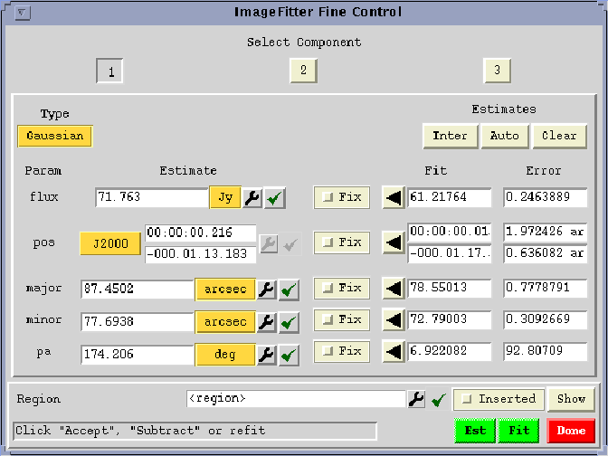
The Advanced Interface
If you activate the advanced interface (via the ``Fine Control'' rollup and the ``Go'' button), then
With the advanced interface, the order in which you do things is not as linear as with the basic interface. However, the idea is that you first establish an estimate for each component, and then do the fit.
Here is an example of the advanced Imagefitter GUI with three components available.
You select a particular component by clicking on the numbered (TAB) button at the top of the GUI (this is a pseudo-tab widget interface). This brings to the front a GUI for this particular component. You then choose the type of component you wish to fit (optionmenu in the top left). Then you establish an estimate for each component and then fit them simultaneously in a specified region.
At the bottom of the advanced GUI, there is a Region widget. This houses any region you create interactively with the main display (via the rectangle or polygon region maker). This region is used in two ways. Firstly, this is the region that is used when you press the ``Fit'' button. Secondly, when you make an automatic estimate for a particular component, the pixels are only selected from this region. Thirdly, when you make an automatic estimate for all components simultaneously, the region must embrace all of the sources of interest (it would be the same region as when doing the actual fit). Thus the region has a context dependent use - one component specific (auto individual component estimate) and one global (the fit and auto estimate for all components). If you have not explicitly set a region, it defaults to the unzoomed full region currently being displayed.
To aid you in using this Region widget, there is a check button (labelled ``Inserted'') which is set on for half a second when a region is captured from the main display. There is also a button labelled ``Show''. This lists the bounding box of the region and redisplay the region on the image.
Now the main thing you must do is establish an estimate for that component. You can do this in a variety of ways. Firstly, you can enter manually the values for each parameter. Secondly, you can press the ``Auto'' button and an automatic estimate will be made for you. Thirdly, you can press the ``Inter'' button and use the displayed overlay to establish an interactive estimate.
It is also possible to make automatic estimates for *all* of the components (rather than one by one). You do this by establishing a region that embraces all of the components. Then press the ``Est'' button at the bottom and it will make an estimate for each component requested. It won't work terribly well if the components are heavily overlapping.
Once you are happy with the estimates for each component, you press the ``Fit'' button. You can then click the ``Accept'' button on the main GUI display (as in the Basic interface) if you want to keep the fit, or you can just do another one.
The buttons labelled ``Fixed'' for each parameter enable you to fix that parameter at its estimated value during the fit. This must be an active value to be useful. To aid in setting an estimated value which you wish to fix, the left-pointing arrows transfer the values from the fit entry boxes to the estimate boxes.
The ``Pixel Selection'' rollup is active for the Advanced as well as the Basic interface.
Finally please note that for your convenience, the flux density is presented to you by the Imagefitter GUI interfaces as a peak flux density. Inside the Componentlist, the flux density is stored in an Integral representation. Therefore conversions back and forth go on behind the scenes.
Events
The Imagefitter emits one event called 'accept'. Whenever the user presses the 'Accept' button to accept a fit, this event is emitted. The value of the event is the fit number.